DESIGNATION | 24 KV VOLTAGE | 36 KV VOLTAGE |
Nominal Volatage (kV) | Up to 24kV | Up to 36kV |
Industrial frequency (Hz) Industrial frequency withstand voltage: | 50Hz / 60Hz 28kV (à 12kV) – 50kV (à 24kV) – 60 (24kV) | 50Hz / 60Hz 70kV (à 36kV) |
Lightning impulse withstand voltage (kV) – Insulation (Nominal lightning impulse resistance voltage (kV)): Lightning impulse withstand voltage (kV) – Insulation (Nominal lightning impulse resistance voltage (kV)): – Sectioning (Separation interval (between contact, in open position) (kV)): – Sectioning (Separation interval (between contact, open position) (kV)): | 75kV (à 12kV) – 125kV (à 24kV) 85kV (à 12kV) – 145kV (à 24kV) | 170kV (à 36kV) 195kV (à 36kV) |
Permissible short-time current (KA) | 21kA/3 sec. | 16kA/1 sec |
Rated cell current (A): – IS arrival or departure cells – Cells protected by PF fuse | 400-630 200 | 400-630 200 |
Rated nominal current of the busbar (A) | 400-630 | 400-630 |
Degree of protection of the enclosure | IP3X | IP3X |
Degree of protection of the tank | IP68 | IP68 |
Cable entry | Cable entry Bottom entry | Cable entry Bottom entry |
Internal Arc Class (IAC) | IAC-AFL | IAC-AFL |

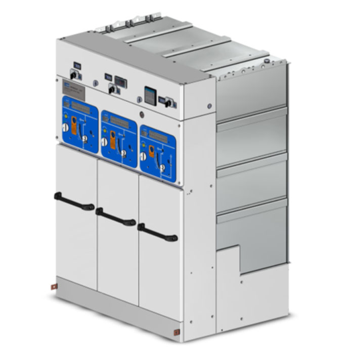
The cell and the busbar are contained in a stainless steel tank filled with SF6 at 0.03MPa (relative) pressure to ensure the insulation functions.
Sealed for life, the vessel must satisfy the criterion of a “sealed pressure system”, in accordance with standard IEC 62271-1 (§ 3.6.5.4): a system for which no gas manipulation is required during the 40 years of shelf life and at 40°C. Thus no filling valve is required. In addition the manufacturer will confirm that the maximum loss is less than 0.1% per year.
The fully filled tank makes the switches insensitive to the environment (temporary flooding, high humidity, etc.), with an IPX7 degree of protection in accordance with standard IEC 60529 §14.2.7.
When the device is finished, the active parts of the breaking devices are maintenance-free and the control panel is low-maintenance.
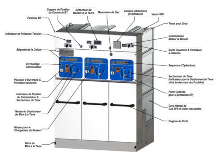
Each device identified by a clear label indicating the functions and electrical characteristics in accordance with IEC 62271-1.
The device and the control panel will be made in such a way that the position of the various switching devices is visible to the operator on the front of the control panel.
In accordance with applicable standards, the device is designed to prevent any access to live parts in service without the use of a tool.
Dielectric medium
SF6 gas is the preferred dielectric medium for RMU type devices.
Absorbent materials will be integrated into the tank to trap the residues and regenerate the SF6 gas after an arc generated by a cut in the device.
Grounding
The cables must be earthed by an earthing switch with full making capacity in accordance with standard IEC 60271-102. The earthing switch can only be used if the loop switch is open.
A mechanical interlock system prevents access to the operating port to prevent operator error such as closing the ground when the loop switch is closed.La mise à la terre sera actionnée par son propre mécanisme de fermeture et la fermeture manuelle se fera avec un mécanisme à action brusque, indépendante de l’opérateur.
Interrupteur
They will be maintenance free and of the reduced pressure SF6 type. The position of the power and grounding contacts will be clearly visible on the front of the control panel. The position indicator provides positive contact indication in accordance with IEC 62271-103.
The switches are of the “increased operating frequency” type in accordance with standard IEC 62271-103.
The opening and closing operations are carried out using a snap action mechanism independent of the operator.
Each switch can be motorized on site without modification of the control mechanism and switch energized but open.
The switch and earthing switch mechanism has a mechanical endurance of at least 1000 operations.
The bushings are located to work with the cables specified and allow for the connectors of these cables in accordance with the instructions supplied for 630A M16 (Interface-C) for incoming & outgoing side; and 250A plug-in type (Interface-A) for switch & fuse combination side.
The type of cable terminals will be in accordance with the EN-50181 standard.

Low Voltage Panel

Rectifier (Battery Charger)
